A WORK IN PROGRESS
PIC 16F690 Engine Timer
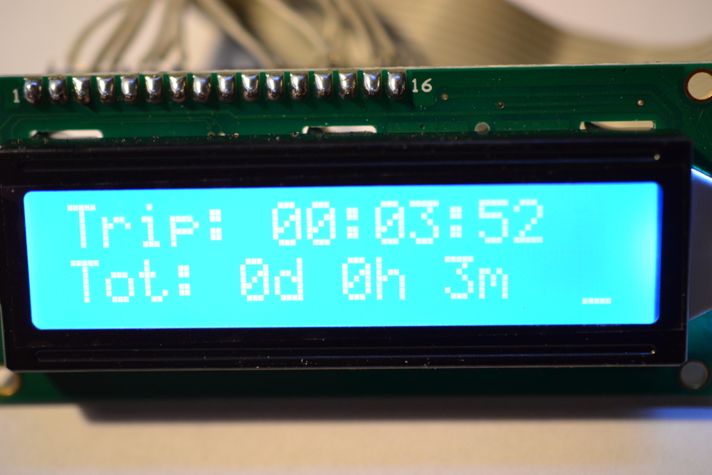
This is a timer circuit, using the PIC 16F690s timer and EEPROM. When it's powered on, A short message is shown, and it starts to count seconds. Seconds are getting into minutes, and minutes are getting into hours. Hours are getting into days.
The hardware
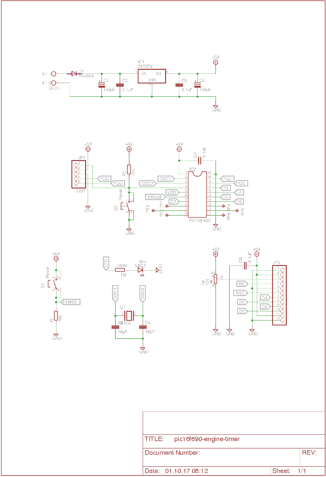
Click here for a bigger view.
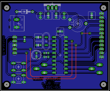
When the schematic is done, it's time to do some PCB layout design. This is a tedious job, and I usually spend a few days doing it. After the schematic is done, I do a preliminary layout of the board. Then I wait a day or two, and then I pick up where I left. Often I see some stupid mistake. But in the end. I pretty satisfied with the board, and I etch it.
This layout is what I ended up with.
Parts, package and libraries:
Part     Value          Device          Package      Library      Sheet

C1       100uF          CPOL-EUE2.5-5   E2,5-5       rcl          1
C2       18pF           C-EU025-050X050 C025-050X050 rcl          1
C3       0.1uF          C-EU025-050X050 C025-050X050 rcl          1
C4       18pF           C-EU025-050X050 C025-050X050 rcl          1
C5       0.1uF          C-EU025-050X050 C025-050X050 rcl          1
C6       100uF          CPOL-EUE2.5-5   E2,5-5       rcl          1
C7       0.1uF          C-EU025-050X050 C025-050X050 rcl          1
C8       0.1uF          C-EU025-050X050 C025-050X050 rcl          1
D1       1N4004         1N4004          DO41-10      diode        1
IC1      7805TV         7805TV          TO220V       linear       1
IC2      PIC16F690      DIL20           DIL20        ic-package   1
JP1      ICSP           PINHD-1X5       1X05         pinhead      1
JP3                     PINHD-1X12      1X12         pinhead      1
LED1     Grn            LED5MM          LED5MM       led          1
Q1       8MHz           XTAL/S          QS           special      1
R1       10K            R-EU_0204/2V    0204V        resistor     1
R2       100R           R-EU_0204/2V    0204V        resistor     1
R3       10K            R-EU_0204/2V    0204V        resistor     1
R4       10K            TRIM_EU-LI10    LI10         pot          1
S1       Reset          10-XX           B3F-10XX     switch-omron 1
S2       Reset          10-XX           B3F-10XX     switch-omron 1
TP1      TPPAD1-13Y     TPPAD1-13Y      P1-13Y       testpad      1
TP2      TPPAD1-13Y     TPPAD1-13Y      P1-13Y       testpad      1
TP3      TPPAD1-13Y     TPPAD1-13Y      P1-13Y       testpad      1
TP4      TPPAD1-13Y     TPPAD1-13Y      P1-13Y       testpad      1
TP5      TPPAD1-13Y     TPPAD1-13Y      P1-13Y       testpad      1
TP6      TPPAD1-13Y     TPPAD1-13Y      P1-13Y       testpad      1
X1       12vDC          W237-102        W237-102     con-wago-500 1
Some pictures
Software
When the hardware is all done, and every component is soldered on, it's time for the software.
// INCLUDING LIBRARIES
#include <xc.h>
#include <stdio.h>
#include <stdlib.h>
#include <string.h>
#include <stdbool.h>

// CONFIGURATION BITS
#pragma config FOSC = XT        // Oscillator Selection bits (HS oscillator: High-speed crystal/resonator on RA4/OSC2/CLKOUT and RA5/OSC1/CLKIN)
#pragma config WDTE = OFF       // Watchdog Timer Enable bit (WDT disabled and can be enabled by SWDTEN bit of the WDTCON register)
#pragma config PWRTE = OFF      // Power-up Timer Enable bit (PWRT disabled)
#pragma config MCLRE = ON       // MCLR Pin Function Select bit (MCLR pin function is MCLR)
#pragma config CP = OFF         // Code Protection bit (Program memory code protection is disabled)
#pragma config CPD = OFF        // Data Code Protection bit (Data memory code protection is disabled)
#pragma config BOREN = ON       // Brown-out Reset Selection bits (BOR enabled)
#pragma config IESO = ON        // Internal External Switchover bit (Internal External Switchover mode is enabled)
#pragma config FCMEN = ON       // Fail-Safe Clock Monitor Enabled bit (Fail-Safe Clock Monitor is enabled)

#pragma warning disable 373     // disable warning 373
#pragma warning disable 359     // disable warning 359
#pragma warning disable 355     // disable warning 355

// DEFINITIONS
#define _XTAL_FREQ  8000000     // Compiler reference
#define LCD_RS      RA2         // LCD Register Select pin
#define LCD_EN      RA1         // LCD Enable pin
#define LCD_DATA    PORTC       // LCD datapins are connected here
#define number      0x30        //

// VARIABLES
volatile char counter, buffer[3];
volatile int
    seconds = 0,
    minutes = 0,
    hours = 0,
    tot_days = 0,
    tot_hours = 0,
    tot_minutes = 0;
unsigned int len, i;
unsigned char days_adr = 0x00;
unsigned char hours_adr = 0x10;
unsigned char minutes_adr = 0x20;

// FUNCTION PROTOTYPE
void interrupt ISR();
void check_for_erase();
unsigned char eeprom_read_data(unsigned char address);
void eeprom_write_data();
void eeprom_writestr(unsigned char msg[], unsigned char address);
void lcd_clear();
void lcd_goto(unsigned char pos);
void lcd_init();
void lcd_putch(char c);
void lcd_puts(const char* s);
int lcd_strobe(void);
void lcd_write(unsigned char c);
void osc_init();
void read_total_run_time();
void short_welcome();
void show_time();
void timer_init();
void update_time();
void show_total_time();
void write_time_to_eeprom();

// FUNCTIONS
// Function to strobe LCD, "pings" the En-pin
int lcd_strobe(void)
{
    LCD_EN = 1;
    __delay_us(1);
    LCD_EN = 0;
}

// Function to write on the LCD
void lcd_write(unsigned char c)
{
    __delay_ms(1);
    LCD_DATA = ((c >>4) & 0x0f);
    lcd_strobe();
    LCD_DATA = (c & 0x0f);
    lcd_strobe();
}

// Function to reset/clear the LCD
void lcd_clear(void)
{
    LCD_RS = 0;
    lcd_write(0x1);
    __delay_ms(1);
}

// Function to write a string to the LCD
void lcd_puts(const char *s)
{
    LCD_RS = 1;
    while(*s)
        lcd_write(*s++);
}

// Functionto write one char on the LCD
void lcd_putch(char c)
{
    LCD_RS = 1;
    lcd_write(c);
}

// FUnction to place cursor on the LCD
void lcd_goto(unsigned char pos)
{
    LCD_RS = 0;
    lcd_write(0x80+pos);
}

// Function to initialze the LCD
void lcd_init(void)
{
    char init_value;
    init_value = 0x3;

    LCD_RS = 0;
    LCD_EN = 0;

    __delay_ms(15);

    LCD_DATA = init_value;
    lcd_strobe();    __delay_ms(10);
    lcd_strobe();    __delay_ms(10);
    LCD_DATA = 2;
    lcd_strobe();
    lcd_write(0x0e);    // display on, cursor on, blink off
}

// Function to initialize the oscillator
void osc_init(void)
{
    OSCCONbits.IRCF = 0b111;    // 8MHz
    OSCCONbits.OSTS = 1;        // Running from Fosc in config/ External clock
    OSCCONbits.HTS  = 1;        // stable
    OSCCONbits.SCS  = 0;        // Clock source def by Fosc

    return;
}

// Function to handle timer 1 interrupts
// Counter = Fosc/instruction cycle * prescaler * timer1 resolution
// Counter = 8MHz / (4 intrstructions pr cycle * 1 prescaler value * 2^16resolution)
// Counter = 8000000 / (4 * 1 * (2^16))
// Counter = 30.51
void interrupt ISR()
{
    if (PIR1bits.TMR1IF == 1)       // Timer1 overflow interrupt flag
    {
        counter++;
        if (counter == 30)          // Check if TMR1 have overflown
        {
            PORTCbits.RC5 ^= 1;     // Toggle LED
            update_time();
            show_time();
            show_total_time();
            write_time_to_eeprom();
            counter = 0;            // Reset counter
        }
        PIR1bits.TMR1IF = 0;        // Clear the overflow flag
    }
    if (PORTCbits.RC4)              // Check if RC4 is high
    {
        lcd_clear();
        check_for_erase();
    }
}

// Function to initialize the timer
void timer_init()
{
    TMR1H = TMR1L = 0;          // Clear TMR1H and TMR1L
    T1CONbits.T1CKPS1 = 0;      // Prescaler 1:1
    T1CONbits.T1CKPS0 = 0;      // Prescalre 1:1
    PIE1bits.TMR1IE = 1;        // TMR1 overflow interrupt enable bit
    T1CONbits.TMR1ON = 1;       // Timer 1 on
    INTCONbits.PEIE = 1;        // Enable perepherial interrupt
    INTCONbits.GIE = 1;         // Enable global interrupt
}

// Function to show initial information
void short_welcome(void)
{
        lcd_clear();
        lcd_goto(0);
        lcd_puts("  Engine timer  ");
        lcd_goto(0x40);
        lcd_puts("    ver 0.1a    ");
        __delay_ms(3000);
        lcd_clear();
}

// Function to show the time
void show_time()
{
    lcd_goto(0);
    lcd_puts("Trip: ");
    itoa(buffer, hours,10);
    if (hours < 10)
    {
        lcd_puts("0");
    }
    lcd_puts(buffer);
    lcd_puts(":");
    itoa(buffer, minutes, 10);
    if (minutes < 10)
    {
        lcd_puts("0");
    }
    lcd_puts(buffer);
    lcd_puts(":");
    itoa(buffer, seconds, 10);
    if (seconds < 10)
    {
        lcd_puts("0");
    }
    lcd_puts(buffer);
}

// Function to display the total run time
void show_total_time()
{
    lcd_goto(0x40);
    lcd_puts("Tot: ");

    itoa(buffer, tot_days, 10);
    lcd_puts(buffer);
    lcd_puts("d ");

    itoa(buffer, tot_hours, 10);
    lcd_puts(buffer);
    lcd_puts("h ");

    itoa(buffer, tot_minutes, 10);
    lcd_puts(buffer);
    lcd_puts("m  ");
}

// Function to update the time
void update_time()
{
    seconds++;
    if (seconds == 60)
    {
        minutes += 1;
        tot_minutes += 1;
        seconds = 0;
    }
    if (minutes == 60)
    {
        hours += 1;
        minutes = 0;
    }
    if (hours == 24)
    {
        hours = 0;
    }

    if (tot_minutes == 60)
    {
        tot_hours += 1;
        tot_minutes = 0;
    }
    if (tot_hours == 24)
    {
        tot_days += 1;
        tot_hours = 0;
    }

}

// Function to write the total run time to eeprom.
void write_time_to_eeprom()
{
    itoa(buffer, tot_days, 10);
    eeprom_writestr(buffer, days_adr);
    if (tot_days < 10)                      // CHeck if buffer is > 10
    {
        EEADR = 0x01;                       // If so, write 0xFF
        EEDATA = 0xFF;                      // To the second day_adr
        eeprom_write_data();
    }

    itoa(buffer, tot_hours, 10);
    eeprom_writestr(buffer, hours_adr);
    if (tot_hours < 10)
    {
        EEADR = 0x11;
        EEDATA = 0xFF;
        eeprom_write_data();
    }

    itoa(buffer, tot_minutes, 10);
    eeprom_writestr(buffer, minutes_adr);
    if (tot_minutes < 10)
    {
        EEADR = 0x21;
        EEDATA = 0xFF;
        eeprom_write_data();
    }
}

// Function to write data to EEPROM
void eeprom_write_data()
{
EECON1bits.EEPGD = 0;   // Program or data memory access bit. 0 = access data
EECON1bits.WREN = 1;    // Write enable bit
INTCONbits.GIE = 0;     // Disable gloab interrupt
INTCONbits.PEIE = 0;    // Disable perepherial interrupt
EECON2 = 0x55;          // Has to be written, read the manual
EECON2 = 0xAA;          // Has to be written, read the manual
EECON1bits.WR = 1;      // Write control bit. 1 = initiate write cycle
INTCONbits.GIE = 1;     // Enable global interrupt
INTCONbits.PEIE = 1;    // Eneable perepheral interrupt
while (!PIR2bits.EEIF); // EE Write operation interrupt flag
PIR2bits.EEIF = 0;      // Write operation has not completed or has not started
}

// Function to write a string to the EEPROM
void eeprom_writestr(unsigned char msg[], unsigned char address)
{
    len = strlen(msg);
    for (i=0; i<len; i++)
    {
        EEADR = address + i;        // EEADR -> Actual memory address
        EEDATA = msg[i];            // EEDATA -> Data to be written
        eeprom_write_data(msg[i]);
    }
        EECON1bits.WREN = 0;        // Write enable bit
}

// Function to read from teh EEPROM
unsigned char eeprom_read_data(unsigned char address)
{
    volatile unsigned char retval;
    unsigned char save_gie;
    save_gie = INTCONbits.GIE;
    EEADR = address;            // EEPROM address to be read
    EECON1bits.RD = 1;          // EEPROM Read control bit. 1 = initiate a memory read
    retval = EEDATA;            // Read value
    return retval;
}

// Function to erase EEPROM data
void check_for_erase()
{
    T1CONbits.TMR1ON = 0;           // Turn TMR1 off
    lcd_puts("   ERASE ALL!   ");
    EEDATA = 0xFF;                  // Value to write
    EEADR = 0x00;
    eeprom_write_data();
    EEADR = 0x01;
    eeprom_write_data();
    EEADR = 0x10;
    eeprom_write_data();
    EEADR = 0x11;
    eeprom_write_data();
    EEADR = 0x20;
    eeprom_write_data();
    EEADR = 0x21;
    eeprom_write_data();
    __delay_ms(1000);
    lcd_goto(0x40);
    lcd_puts("  PRESS RESET.  ");
    while(1);
}

// Function to read EEPROM and the total run time, in seconds
void read_total_run_time()
{
    buffer[0] = eeprom_read_data(0x00);
    buffer[1] = eeprom_read_data(0x01);
    tot_days = atoi(buffer);                // Convert the data to int so we can do some math

    buffer[0] = eeprom_read_data(0x10);
    buffer[1] = eeprom_read_data(0x11);
    tot_hours = atoi(buffer);

    buffer[0] = eeprom_read_data(0x20);
    buffer[1] = eeprom_read_data(0x21);
    tot_minutes = atoi(buffer);


}

// MAIN PROGRAM
void main(void) {
    TRISA = 0b00000000;     // TRISA output
    PORTA = 0b00000000;     // PORTA low

    TRISB = 0b0000;         // RX+TX = in, rest out
    PORTB = 0b0000;         // PORTB low

    TRISC = 0b00010000;     // RC4 set to input -> Erase button
    PORTC = 0b00000000;     // PORTC low

    ANSEL = 0;              // Disable the input buffer on ANSEL
    ANSELH= 0;              // Disable the input buffer on ANSELH

    CM1CON0 = 0;            // Comparator C1 control register 0,  disabled
    CM2CON0 = 0;            // Comparator C2 control register 0, disabled

    osc_init();             // Initialize the oscillator
    lcd_init();             // Initialize the LCD

    short_welcome();        // Show welcome

    read_total_run_time();  // Read total run time from eeprom

    timer_init();           // Initialize and start the timer

    while(1)                // Do this forever...
    {
        // nothing to do, everything is done with timer1/interrupt
    }
    return;
}
Pictures
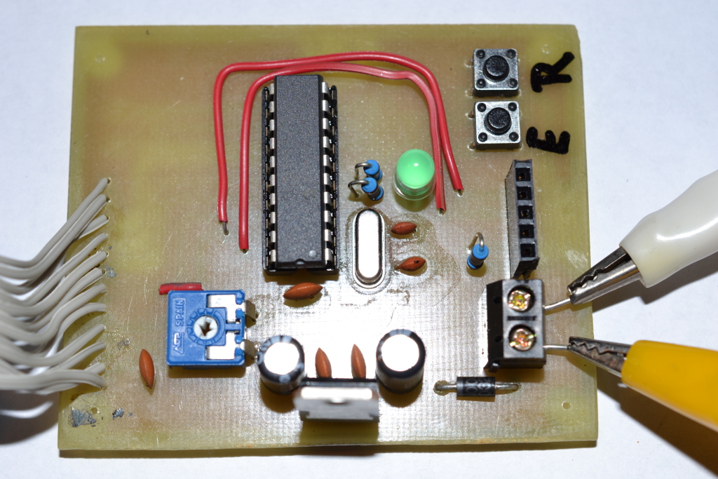
Pictures tells a thousand words:
This is the component side of the circuit.
This is the LCD.