A work in progress
Remote controlled rudder
In this article, I'll make a remote controller, to steer my boat's rudder. This way, I can sit on the deck, and steer the boat. This is my preliminary specifications:
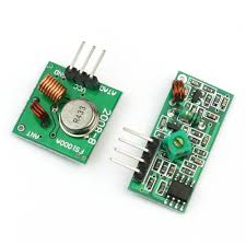
The handheld unit is obviously going to be powered by AA batteries. It will have an RF module connected to it, so I'll be able to move freely on deck. It'll have two buttons for Port and Starboard navigation. I'd like the transmitter to be as small as possible, and wrapped in a small casing. That way, I might be able to hag it around my neck. The transmitter will be a 433MHz module from Ebay. This is the transmitter and receiver:
The unit that's connected to my rudder, will have a threaded rod, and a DC motor connected to it. It will need an H-bridge and a RF receiver. An LCD display to show various info would also be nice.
I will use a PIC 16F628a microcontroller on both the handheld, and the motor controller.
The transmitter
The circuit is fairly straight forward. A voltage regulator regulates the power down to 5vDC to the MCU. A transistor turns the RF RX module on and off, according the the button that is pressed. Portside is for left and Starboad is for right. The LED is the response to the user, telling the user that the module is transmitting.
The Software
The software listing below, is really simple. All that is done, is when a button is pressed, a value is sent out the TX pin on the PIC.
// CONFIG
#pragma config FOSC = HS        // Oscillator Selection bits (HS oscillator: High-speed crystal/resonator on RA6/OSC2/CLKOUT and RA7/OSC1/CLKIN)
#pragma config WDTE = ON        // Watchdog Timer Enable bit (WDT enabled)
#pragma config PWRTE = OFF      // Power-up Timer Enable bit (PWRT disabled)
#pragma config MCLRE = ON       // RA5/MCLR/VPP Pin Function Select bit (RA5/MCLR/VPP pin function is MCLR)
#pragma config BOREN = ON       // Brown-out Detect Enable bit (BOD enabled)
#pragma config LVP = ON         // Low-Voltage Programming Enable bit (RB4/PGM pin has PGM function, low-voltage programming enabled)
#pragma config CPD = OFF        // Data EE Memory Code Protection bit (Data memory code protection off)
#pragma config CP = OFF         // Flash Program Memory Code Protection bit (Code protection off)

// INCLUDES
#include <xc.h>
#include <stdlib.h>
#include <stdio.h>

// DEFINES
#define _XTAL_FREQ 8000000     // COmpiler use 8MHz oscillator
#define port_btn  PORTAbits.RA0         // Button to move to port side
#define starboard_btn PORTAbits.RA1     // Button to move to starboard
#define port_led PORTAbits.RA2          // Feedback to user -> move to port
#define starboard_led PORTAbits.RA3     // Feedback to user -> move to starboard
#define rf_module PORTBbits.RB0        // RF module power control

#pragma warning disable 373
// VARIABLES

// FUNCTION PROTOTYPES
void uart_init(void);
unsigned char calculateparity(unsigned char scancode);
void uart_transmit(unsigned int mydata_byte);
void uart_write(const char *txt);

//FUNCTIONS

unsigned char calculateparity(unsigned char scancode)
{
    unsigned char parity = 0;
    while (scancode > 0)
    {
        if (scancode & 0x01)
        {
            parity++;
        }
        scancode = scancode >> 1;
    }
    return (parity & 0x1);
}

void uart_transmit(unsigned int mydata_byte)
{
    while(!TXSTAbits.TRMT);
    TXSTAbits.TX9D = calculateparity(mydata_byte);
    TXREG = mydata_byte;
}

void uart_write(const char *txt)
{
    while(*txt != 0) uart_transmit(*txt++);
}

void uart_init(void)
{
    TXSTAbits.BRGH = 0;     // High baud selection bit
    TXSTAbits.TX9 = 1;      // 9th bit transmit enable
    TXSTAbits.TXEN = 1;     // Transmit enable bit
    TXSTAbits.SYNC = 0;     // Asynchronous moide

    RCSTAbits.SPEN = 1;     // Serial port enable bit
    RCSTAbits.RX9 = 0;      // 9th bit receive bit
    RCSTAbits.CREN = 1;     // Continous receive bit

    SPBRG = 25;     // 4800

    PIE1bits.RCIE = 1;      // Peripheral interrupt enable reigster1->EUSART receive interrupt enable
    __delay_ms(50);         // Wait for settings to settle down.
    return;
}


void main(void) {
    CMCON = 0x07;           // Turn comparators off

    TRISA = 0b00000011;     // RA0 & RA1 input
    TRISB = 0b00000100;     // All but TX output
    PORTA = 0b00000000;     // All low
    PORTB = 0b00000110;     // TX & RX high

    uart_init();

    while (1)
    {
        if (port_btn)
        {
            rf_module = 1;
            __delay_ms(100);
            port_led = 1;
            //printf("p\n\r");
            uart_write("p\n\r");
            rf_module = 0;
            port_led = 0;

        }
        if (starboard_btn)
        {
            rf_module = 1;
            __delay_ms(100);
            starboard_led = 1;
            //printf("s\n\r");
            uart_write("s\n\r");
            rf_module = 0;
            starboard_led = 0;

        }

    }
    return;
}
The receiver
Work in progress...