Python based 0 - 55v DVM
Introduction
You can not have enough Digital Voltage Multimeters, or some other device that measures voltage. Also, I needed an extra voltage measuring device on my boat. This little project teaches you how to make a PIC16F688 read voltage, convert it to an AD value, and then transfer the value to a computer with RS232/TTL. On the computer side, I’m having Python3 running, and a small program that reads the USB-port and calculates the voltage from the AD value. To display the voltage, I’ve made a nice little GUI with TKinter. Maximum input voltage is 55v DC.
Parts
I used a PIC16F688, but you can use any other PIC, as long as it has an AD module. A capacitor to put nearby the PIC, a 10K resistor and two more resistors to make a voltage divider. I used one 10K and a 100K. To help transfer the AD value from the PIC to the PC I used an USB-to-TTL module. You’ll also need a computer or a Raspberry Pi.
Click here for the PIC program.
Click here for the Python program.
Reading the voltage
The PIC is configured and programmed to read voltage on pin7, RC3/AN7. It reads and sends the value at every 125mS. See the source file for more details. The uart functions to the main program are in the libraries. It’s coded in XC8, and the code is well commented.
The AD value is then sent through the USB-to-TTL converter, and to the PC.
Schematic
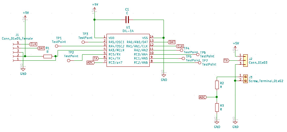
Microchip PICs, and every other MCU’s, can’t handle voltages much higher than 5v DC very well. That’s why we need to have a voltage divider. In the lower right corner in the schematic above, you’ll see the voltage divider. In this case I’m using a resistive divider. A resistive divider in this case is where both impedances are purely resistive. The formula is:

I’ve measured the resistors on the breadboard, to have the most accurate reading. In my case: R2 = 100600 Ohm R3 = 9950 Ohm
An example: The voltage coming into the divider is 18v DC. Using the formula above we get:


Output voltage is 1.62v DC. This is handled very well by the PIC. Another example. Input voltage is 12v DC. Jumping in at number two above:
This is voltages that the PIC can handle. The PIC is reading these voltages, and then converting them with the AD module to an integer. This is an integer in the range of 0 to 1023. That means that there are 1024 numbers. Here it’s easy to mix things up. With this setup we can safely measure voltages from 0 - 55v DC.
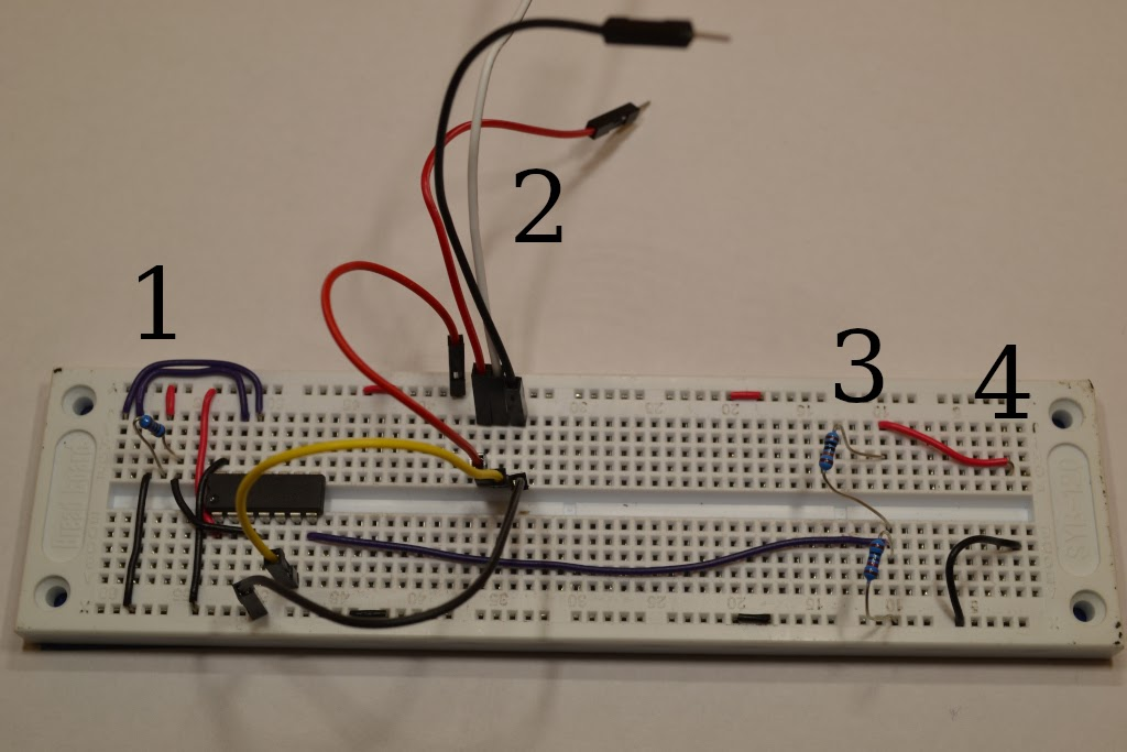
Breadboard
This is what the breadboard looks like. 1. Connection to the ICSP. 2. Wires to USB-to-RS232 3. Voltage divider 4. Connection to the voltage we want to measure. Red = positive, Black = negative/GND
Python and TKinter to display
On the computer, or raspberry Pi, I’ve installed Python3. The small program that’s running, reads the USB port. If the USB port is not found, an error message is displayed. The integer is the raw AD value. The PIC sends it every 125. ms. Then the program calculates the AD value to the actual input voltage. Then we get the voltage, Vin, from the first equation.
Two of the following lines do the calculation, the last is only to format it with two decimals.
vout = (int(reading)* 5.0) / 1024.0
vin = vout / (R2/(R1+R2))
new_volt = ('{0:0.2f}'.format(vin))
The first line calculates the voltage going into the PIC from the voltage divider. The second line uses the voltage and the resistors values, to calculate the input voltage. Let’s play with the example from above. The AD value from the PIC is 332. First we’ll need to convert the AD value back to voltage:

1.62vDC is going into the PIC from the voltage divider. Then we’ll need to calculate the original voltage from the input voltage:

The last line formats the Vin with two decimals.
I’ve used TKinter to make the GUI, like the image shown below.
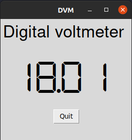
The program uses a try - except loop. The try section tries to read the /dev/ttyUSB0 port. If the port is not found, an exception occurs and a messagebox is shown.
Next step
The next steps would be to put this into a Raspberry Pi, with a 3.5” touch screen. Also, there are a lot of unused pins on the PIC. Maybe use one to a buzzer, and some other to some LEDs? There’s no end to the possibilities.